Some notes on my implementation of "The Bottom-Left Bin-packing Heuristic: An Efficient Implementation" by Chazelle.
(This post didn't end up as polished or complete as I'd hoped, but posting it anyway in hopes it will be useful next time I look at the code.)
General comments
I suspect the proof of O(N^2) in the paper isn't quite correct, though
not sure it affects the results. In the explanation of QWi, it says
Thus, it is important to know which obstacles the right part of the device can encounter when this part starts leaving the subhole and the device is still partially inside it. Since both upper- and right-notches are ruled out,
QNias defined, is the first and only possible obstacle which will stop the motion of the device.
First, that QNi seems to be a typo in the paper and should be QWi,
but in that case there are 2 problems, shown in the following image:
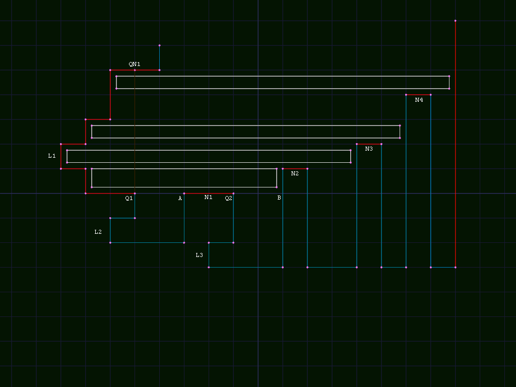
The first problem is that it is ambiguous which point should actually
be QW1, A or B. If QW1 is at A, the edge below A is too
low to actually block anything in subhole L1. If it is at B, it is
also QW2, and we can't make a single link back from B to a Q
node.
The other problem is that QWi doesn't always stop the device, and in
some cases it might need to raise and continue. In the example, there
are 3 rectangles which start inside subhole L1 and extend past
either possible QWi. In 2 cases, the rectangles are only supported
from below by lower notches outside the subhole (N3 or N4). Both
are valid "bottom left" placements, so should be found either while
searching subhole L1 or L3.
To find them from L1, we need to extend FB(L1) to include N2-4
as well as the rightmost edge. In that case, they also need to be
included in FB(L2) in case they are the bottom support of a
placement supported on the left by a vertical edge right of QN1
inside subhole L2.
To find them from L3, it would need to include the entire top edge
starting from L1 in FT(L3) instead of starting at L3, which
doesn't match my understanding of the algorithm.
In either case, it seems like it potentially has to look at some edges more than once per placement. Not sure if the number of those edges is enough to affect the proof of O(N) work per placement or not.
Heuristics
The paper mentions that it works for heuristics that preserve
bottom-left stability, where a placement can't move downwards or
leftwards, and the placements it generates fit that restriction. I
think this can be expanded a bit, in that the data structures work for
placements where there is non-zero contact on at least one edge at the
bottom left corner even if it could slide along that edge. I think the
algorithm could be extended to generate ranges of such placements
instead of strictly "bottom left" placements, though not sure if a
heuristic could efficiently make use of that ability. It still might
be interesting because the popular maxrects algorithm can generate
those placements, so it would allow directly comparing the space/time
complexity of the 2 algorithms with the same set of placements.
The available data for a heuristic with this algorithm is different
from that provided by maxrects, so we can't directly use most of the
popular maxrects heuristics.
A Thousand Ways to Pack the Bin - A Practical Approach to
Two-Dimensional Rectangle Bin
Packing
by Jylänki lists a few options for maxrects heuristics:
Bottom left works directly with Chazelle's algorithm.
Contact Point aka Touching Perimeter translates well to the data
structures stored by Chazelle's algorithm, and is what I am using. I
think calculating full contact length for every potential placement
might add an extra factor of O(N) in worst case (consider placing a
sequence of sets of N squares of size 1/N, where each set of N
squares divides the lower left edge into increasingly finer
stair-steps, so there are always O(N) potential placements.) In
practice, tie-breaker heuristics can be tuned to discourage worst-case
behavior, and due to the properties of the holes in bottom-left
stable placements we can usually avoid a full search of the hole (for
example when searching clockwise, once we go strictly past the top of
the placement there can be no more intersections until a falling
corner or right edge. Similarly searching counter clockwise there can
be no more contacts once strictly past right edge. In both cases, Q
links can also be used to avoid searching the entire edge.)
It might be worth adding a partial contact version, only comparing the contacts adjacent to the lower left corner of the placement, since that can be calculated (with a bit of extra data in the edge descriptions) in approximately constant time instead of O(N) for full contact.
Best Area Fit, Best Short Side Fit, and Best Long Side Fit all
compare the rectangle being placed to the "maximal rectangle" being
considered, so can't be applied directly, but might be useful with
some modifications. If we track bounds for each hole/subhole (useful
for quick rejection of small holes anyway), we can apply the
heuristics to the bounding rectangle, though it probably wouldn't give
as good results as in maxrects.
If also we maintain actual available area in addition to bounds (which
should be trivial in the case where a hole isn't split into multiple
holes, and i think still O(N) when it is split?), Best area fit
would probably be useful.
Similarly, we could compare the length of the short or long dimensions of the rectangle to the length of the corresponding edge(s) supporting it.
In some cases, particularly for unsorted/online packing, it is
probably also worth comparing the sizes of the holes being
considered. Either a Pick Smallest Hole First or modified Best Area
Fit that maintained a total available area for each hole would make
it less likely for a small rectangle to break up a large hole in a way
that prevents fitting a later large rectangle there.
Bin shaping/sizing heuristics
For my main use (texture/font atlases) there is usually a strict upper bound for bin size, but it is frequently much larger than the actual size needed by the rectangles being packed. For example max texture size might be 16384x16384, while a particular font atlas might only need 2000x2000 or so. In that case, many heuristics would pack along bottom and left edges leaving the middle and upper right empty. To avoid that, I add an extra "shaping" heuristic, that adds a penalty to placements depending on how much unused space they would add to the bounds of the active placement area. This can be tuned for various common texture use cases like "must be power of 2 dimensions" required by older hardware, "must be multiples of 4 or 16" for various texture compression formats, or "increase in 256 x 256 blocks" for sparse texturing.
Starting from an active area of 1x1 tends to restrict placements too
much, affecting efficiency. starting with an initial estimate of
sqrt(total-pixels) for offline packing seems to give reasonably good
results. If efficiency needs to be maximized, a few initial sizes
between that and the actual size found can be tried.
Hole vertices
The vertices of a hole are stored as a doubly linked list in clockwise
order, with no intersecting edges. Each vertex stores x and y
coordinates, previous and next links, and optional q flag and
w,n links.
N and W links point from a Qi node to corresponding QNi or
QWi node, or from QNi/QWi back to corresponding Q node.
Q flag indicates whether a node with N or W set is Q or QN/QW.
Special vertices (leftmost edge, left notch or rightmost edge, falling corners) store links back to the corresponding subhole/hole to make it easier to detect which are affected by a given modification.
Additionally, some extra metadata is stored to make it easier to traverse the edge correctly, describing what type of vertical edge the vertex is on, and where.
Possibly should add an extra link from the upper right corner of lower notch to the vertical edge right of that vertex, to optimize finding the lower notches that could support a placement in a particular subhole, though I think that just affects the constant factors, and not overall time complexity.
Subholes / F data structure
For each leftmost edge in a hole, we have a subhole, which
together partition the hole into "nice" areas (plus some extensions).
Each subhole contains a top and bottom edge, both stored as a
sequence of x and y values corresponding to the start point and
the tops of each vertical edge in the (extended) subhole.
For the top edge, we also need to handle the problem of vertical
edges possibly being discontinuous if they contain one or more Q
vertices.
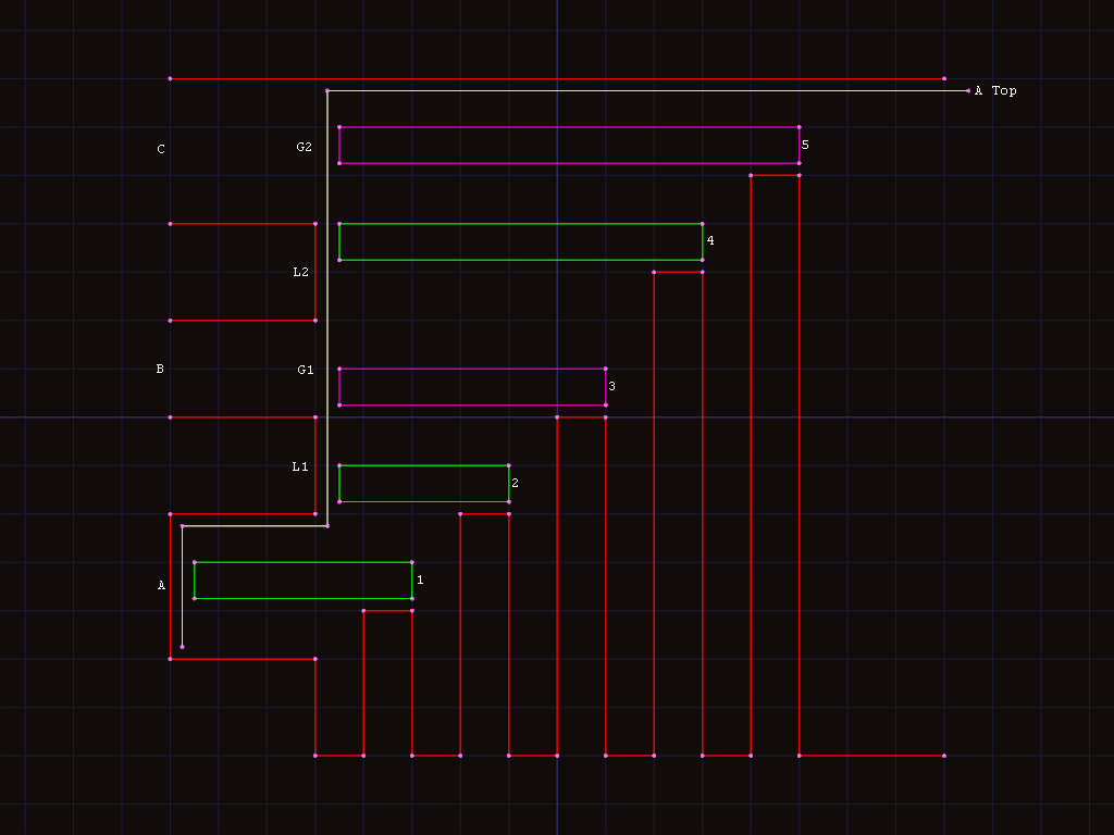
In this example, placements 1,2,4are valid for subholeA.3
and5are not valid (though there may be a valid placement for
subholeBorC), though 3 could be a valid place for a taller
rectangle. To differentiate them, we either need to store 2 vertical
edges (L1andL2) with the sameXcoordinate in thetopedge
for subholeA, or a single vertical edge with 2 gaps (G1,G2`).
While gaps could be tracked by including multiple vertical edges with
the same X value, D is stored as horizontal edges, so it would need
to combine them into something similar to the list of gaps anyway.
The actual top or bottom edge can be reconstructed by forming a
horizontal edge from xn,yn to xn+1,yn then a vertical edge
from that to xn+1,yn+1.
In addition to the top/bottom edges, there are links to the
containing hole, a falling corner if any, and start and end
vertices. Start is the lower vertex of the leftmost edge, and
end is either the Q vertex or the lower vertex of the rightmost
edge of the subhole.
X coordinate of end vertex, and dimensions of bounding box are
also stored for optimization.
Constructing (extended) subholes
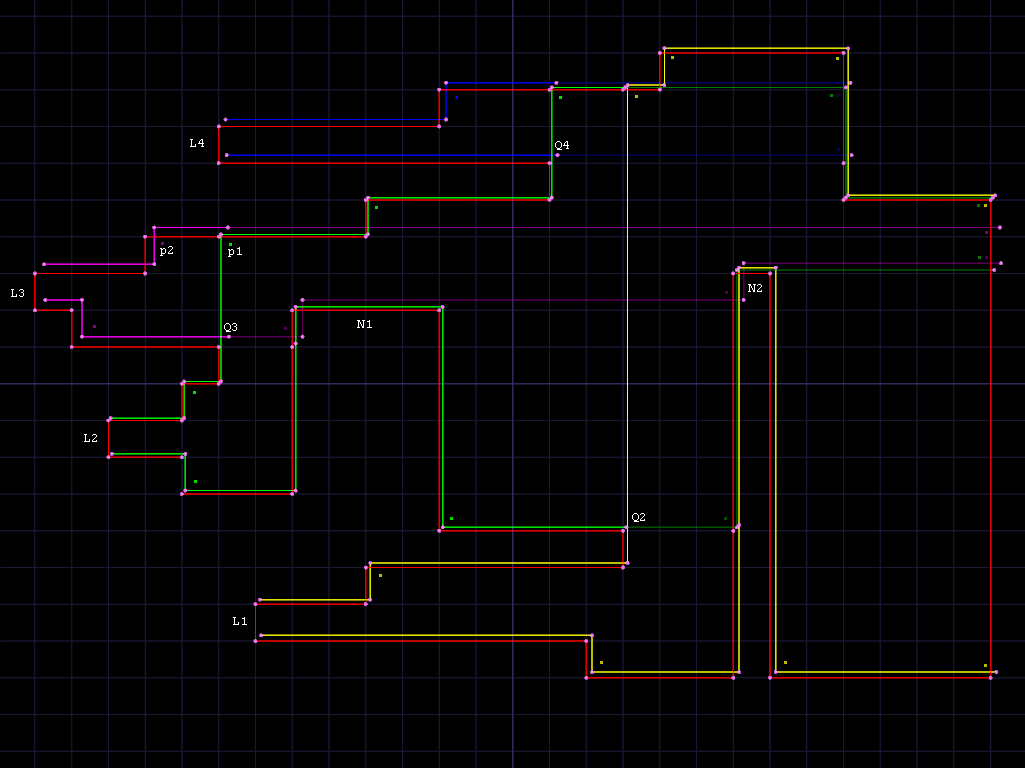
example image based on figure 6 from the paper, with an extra lower notch:
The main hole is drawn in red, with dots at vertices. Each subhole is
drawn in different colors with a different offset up and to right of
the corresponding parts of the main hold. The extension of the subhole
is drawn in a darkened version of the subhole's color. Leftmost
edges are marked L1 - L4, along with corresponding Q2 - Q4
points. Dots mark places we need to check for a given subhole when
placing an object in that subhole.
To build the top/bottom edges, we walk the doubly linked list of
vertices starting at the corresponding part of the leftmost edge for
that subhole, forwards for top and backwards for bottom, looking at
each vertical edge. When walking forwards, we follow all Qi->QNi
links. When walking backwards, we follow Qi->QWi links. In both
cases, we stop when we see a horizontal edge going towards the left.
For the bottom edge, we collect upwards edges until we hit a Qi
point, then we only collect upwards edges with y values greater than
previous Y value. If the Qi->QNi span is completely blocked by a
lower notch to the right, we note that and use that as the right
edge of the subhole, and also note that any falling corner in the
hole can't affect that subhole.
For the top, we collect upwards edges and downwards edges until we hit
the first QNi vertex, then we only collect downwards edges that
cross lower than the QNi vertex, stopping at any early right edge
detected while building bottom edge.
For example, in subhole 2 (L2, green), the top edge follows Q3 and
Q4, and end above Q2, keeping part of the falling edge in the
darker extension. The bottom edge follows both sides of lower notch
N1, and ends at Q2, with extension only following the rising side
of lower notch N2.
Note that we need to be careful at p1, since anything supported by
N1 or N2 should be at p2 in subhole 3, since it can move
left. We still need to check the 2x7 space at p1 before N1 though,
since that is in subhole 2. At p3, anything supported by N2 is
still in subhole 2, since it can't move left into subhole 4.
Similarly, we can't place anything in subhole 1 at p4 supported by
N2, since it could move left to p3 (and possibly down from there,
depending on how wide it is). The gap values are used to check for
that problem.
Subhole 3 (L3, magenta) ends at or above Q3, with top extension
skipping the falling edge, and lower extension raising at N1 and N2.
I don't quite understand how the paper handles cases like N2
blocking placement into the leftmost edge at L3, since it sounds
like it stops at QW2, and doesn't include N2 in subhole 3 at
all. We need to be able to place a 19x1 piece at L3, and fail to place
a 22x1 wide piece there, and also need to be able to place a 22x1
piece at p2 supported by N2, which it seems would be missed with
BOTTOM(B) as described, though i may be missing something.
Calculating D list for a given length
Actual placement uses 2 data structures C and D specialized for a
particular subhole and width L, containing horizontal spans where
the upper or lower left corner of a box could be packed.
D is the list FT of top edges, and mostly corresponds to the
upper-left corners of the top edge of the subhole.
Simple subholes
For subholes without a "falling edge", the calculation is simplified
to just return the horizontal edges bounded by FT. This includes
some space that isn't actually a valid placement in the cases where
L would extend past the right edge of the subhole. This doesn't
matter since the lower list C is also bounded by the same edge, so
would prevent any placements at invalid positions.
The above shows examples of the simple case, with L = 4, with D
shown in red above the subhole, and valid placements shown in green
inside the subhole. Orange lines extending past edge of subhole
indicate invalid placements that would be rejected by corresponding
C data structure.
Subholes with a falling edge
For subholes with a "falling edge", we need to account for situations
where there isn't enough space to place something of width L left of
the falling edge, while keeping the space under the falling edge
available.
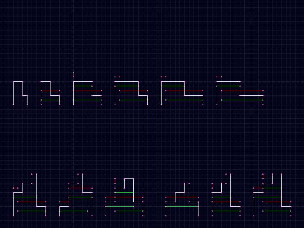
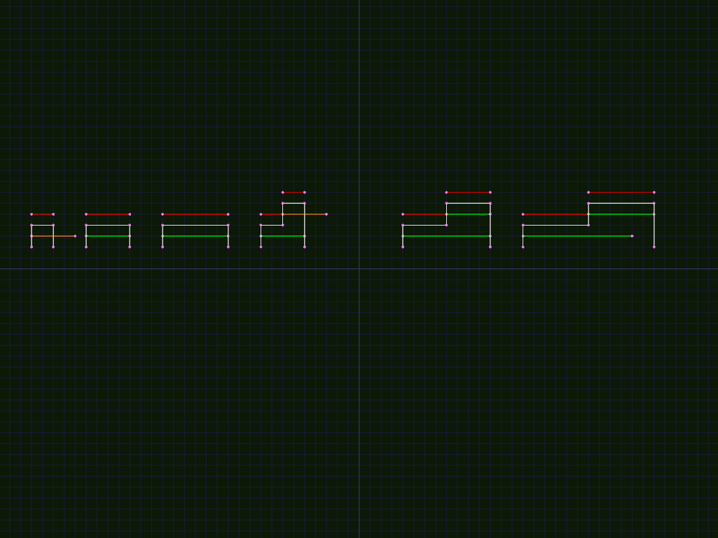
The above example shows some of the cases we need to look at for the complex case, again with red lines above marking the edges in D (with vertical line indicating a 0-width segment), and green indicating the corresponding placement. Note that we sometimes have duplicate positions with different height. In the 3rd example on bottom row, note that it is 3 placements, with the first and last adjacent.
Bottom row is the examples from Fig 12. in the paper, with additional
examples of the special case where the falling edge exactly lines up
with a preceding edge with a gap equal to or narrower than L, or
where there is an exact fit in a span.
Top row shows various simplified versions of them.
In the top row, we have the following cases:
- Doesn't fit at all.
- Hits falling edge before next span.
- exactly fits in next span, then hits falling edge (note 0-length span in output)
- fits in next span, with range of movement = 1, falling edge narrower than
L - fits in next span, with range of movement = 1, falling edge equal to
L - fits in next span, with range of movement = 1, falling edge wider than
L
In all cases, we can allow the span under the falling edge to extend
to the right edge of the subhole for the same reason as the simple
case, since the lower C data structure will reject anything too far
to the right.
In the bottom row, we have the following cases:
- 12a fits in current span, hits falling edge before next span
- 12b fits in current span without hitting falling edge, doesn't fit in next span, but fits under falling edge
- fits in current span, which exactly lines up with falling edge with
gap
L, exactly fits in next span. 3 spans inD, middle one 0 width, first and 3d lined up in Y with 0-length gap. - fits in current span, which exactly lines up with falling edge, gap less than
L. 1 span covering both, or 2 spans with 0-length gap, - 12a with exact fit in current span
- same thing with previous span shown
implementation
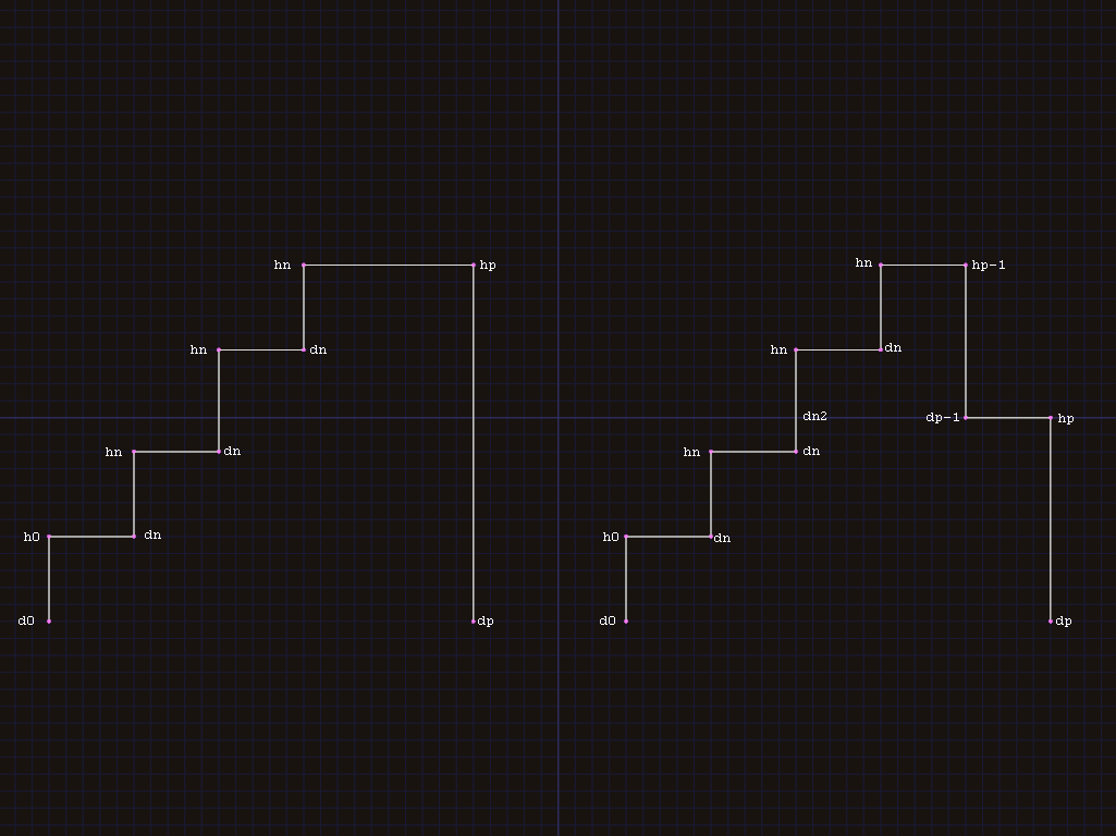
Input for procedure TOP is the width l of the block to be placed,
and the list of vertical edges FT, as pairs Hn,Dn, where n is
from 0 to p, Hn is directly above Dn, and X values increase
with n. We also pass a flag falling indicating whether FT has a
falling edge, and the X coordinate end of the right edge of the
subhole if it is extended. Checking end lets us avoid storing
For the simple case, on the left in image above, most edges dn:hn
(n>=1) are included in output as horizontal edges hn-1:dn. The
final edge is hp-1:hp.
For the case with a falling edge, on right in image above, we have to
check for intersection with dp-1:hp-1 before adding a particular
hn-1:dn pair.
To simplify the logic, we start by checking for l not fitting in the
hole at all.
If l fits between d0 and dp, we have space for at least 1 span,
so we can add h0, and start looping through points dn (n < p-1).
At each dn, we test to see if (<= (+ (x dn) l) (x dp-1)). If so,
we can fit a span at dn+1, so we add dn (as end of horizontal span
from hn-1 added previously) and add hn as start of next span, and
continue loop.
If the next span doesn't fit, we need to check for following options:
falling edge is below current edge. (fig 12a)
In this case, we finish the current span at
(- (x dp-1) l),(y dn), and add a span under the falling edge from(- (x dp-1) l)to(x dp).(- (x dp-1) l)should be at least as large as(x n)if we haven't made any mistakes, but they might be=if the span's width is exactlyl.falling edge is exactly same height as current edge
In this case, the span can continue until
(x dp)since the support continues from the current edge to the bottom of the falling edge.falling edge is above current edge. (fig 12b)
In this case, we finish this span as normal, then find the vertical edge
dn2left of the falling edge, and if there is at leastlbetween that anddp, add a span under the falling edge, from(x dn2),(y dp-1)to(x dp)
Calculating C list for given length.
C is the parts of list FB of bottom edges which could support a
placement of width l.
In addition to the details in the paper, we also store a flag indicating whether a given point is a "bottom left" corner, an "open" point, or "normal".
"Bottom left" is set for the first span, and when the preceding span
is higher than the current span. When set, we have a support to the
left of the span in FB, and can place something at that exact
coordinate if there is enough vertical space.
"Open" is set at the beginning of spans that start l before a
support, and at the end of spans that reach the end of the support. If
a point is marked "open", we can't place anything exactly at that
point since it isn't actually supported.
If a span isn't started with a "bottom left" point, we can't place
things along the span unless supported to the left by an edge from
FT (taking into account that gaps left by subholes can't support the
left edge).
"horizontal edges" in setup
The paper describes the horizontal edges handled by SETUP as "an
ordered list of its horizontal edges {(lk,rk}), with the
correspondence rk = hk+1". This isn't quite clear about what happens
to the edges followed by a rising vertical edge (li-1 in fig 11.c,
if there is a rising edge at i, where rk would have to be di =
dk+1).
It looks like "rk = hk+1" is true for all of the edges we care about, except for possibly the last one, so we may need to handle that one specially.
In Fig 11.d, if the edge at end were falling, or further to the
right, we would need to add the span before it since it might be able
to fall from s3 in that case (and since setup doesn't pay attention
to X values, it always needs to add it)
TODO: images for above?
TODO: figure out if there are any additional things to note about C.
Placing
Not sure if I changed other parts too much, or just don't understand
the algorithm for PLACING in the paper. Doesn't look too hard to
rewrite from scratch though.
Our inputs are the height h to be placed, and lists C and D
containing places where the specified width fits in the bottom and top
respectively of the subhole.
Both should start at same x value. Probably with (y D) > (y C)
depending on how TOP and BOTTOM were implemented, though we won't
rul out starting at same y value for now.
The first possible placement is at the left of the first segment of
C, which is valid iff (y D) - (y C) >= h.
If we place something there, any other placement on that span is
invalid since it could slide to the left (we know from proof in paper
that there are no upper notch edges in the hole, so there can't be
an obstructions at the top that would allow it to sit on that span but
still be blocked from sliding left). In that case, we can move to the
next span on the bottom edge, skipping any spans from top edge with
lower x value. From there we restart checking distance between C
and D at that point.
If we can't place something at the left of the span, we need to follow the 2 edges until either we hit the end or there is enough space for the placement.
At that point, we need to do some extra checks to determine if that
placement is valid, since there can be gaps in the left edge
represented by the top edge (if there was a subhole removed from that
edge). If the entire h fits within a gap, the placement is invalid,
otherwise we add the placement. In either case, we skip to next span
on bottom edge, advance top to match, and restart checking the
distance between C and D.
There are some edge cases we need to be careful about, due to < vs
<= and similar.
Given 3 spans I,J,K on the bottom edge, consider placing at J.
If
Iis lower thanJ, we can't place something exactly at the start of the span. IfIdoesn't exist or is higher, we can place something exactly at the start of the span.If
Kis higher thanJ, we can place something exactly at the end of the span, but ifKis lower, we can't.
On the top edge, we only look at the left edge (TOP doesn't
calculate right edges accurately), and can always place exactly at the
start of the span.
dynamic updates of data structures
I ended up skipping dynamic update of individual subholes for now, and
just rebuild all subholes for any hole that is modified. I think it is
still O(N), just tends towards the worst case compared to partial
updates. Seems to still perform reasonably well though.
If we rebuild the subholes and related data structures from scratch every time, that just leaves updates to the actual hole data structure.
Since I calculate the intersection of the placement and hole for the
placement heuristic, the intersection calculated there is stored and
used to update the hole geometry as well. The intersection is stored
as a set of contiguous contact and gap spans along the border of
the placement.
With that representation, there are 3 cases to consider:
If there is a single
contactspan with nogap, we completely filled a hole and can remove it from the active list.If there is a single
gapspan (which means there is also a singlecontactspan), we have a simple contact that just shrinks the hole.In that case, we add vertices to the hole at the ends of the contact if needed, then remove any internal points in the
contactspan, then add the points from thegapspan.If there are multiple
gapspans, we need to split the hole into multiple holes, adding 1 new hole for each gap after the first.Similarly to the single-gap case, we remove internal points in the
contactspans, then swap the connections at the ends of the gaps so thegapspans are closed and each corresponds to a separate hole, then add any intermediate points fromgapspans.